21.1 RLC Circuits | General Physics
Chad provides a comprehensive lesson on RLC circuits which have a resistor, an inductor, and a capacitor in series with an AC generator. The lesson begins with a discussion of resistors in AC circuits and how power is dissipated when current flows through a resistor in either direction. The voltage across and current through a resistor are in phase. With the change in direction for the flow of current in a circuit, the average current in the circuit will be zero as will the average voltage. The rms voltage and current are introduced which are a sort of average which can be used to calculate the power dissipated in resistor in an AC circuit.
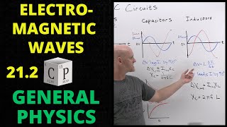
Capacitors in AC circuits are discussed next. The voltage across and current flowing around a capacitor are not in phase as the voltage lags the current by 90 degrees. The effective resistance associated with a capacitor in an AC circuit is called the capacitive reactance, the formula for which is presented and discussed.
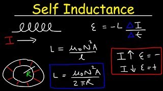
Inductors in AC circuits are discussed next. The voltage across and current flowing through an inductor are not in phase as the voltage leads the current by 90 degrees. The effective resistance associated with an inductor in an AC circuit is called the inductive reactance, the formula for which is presented and discussed.
RLC series circuits are finally discussed, the effective resistance for which is termed the impedance. Chad introduces phasor diagrams which are useful for calculating the voltage and impedance of an RLC series circuit since the voltage across a resistor, inductor, and capacitor are not in phase. As a result, the voltage output of the AC generator in the circuit is not simply the sum of the voltage across the resistor, inductor, and capacitor. The phase shifts relative to one another must be factored in, and the phasor diagram facilitates this. These voltages are added as vectors, and the formula for the maximum voltage is presented. The phasor diagrams can also be used to calculate the overall impedance of the circuit in similar fashion as the vector sum of the resistance of the resistor, the inductive reactance of the inductor, and the capacitive reactance of the capacitor.
Finally, Chad shows how to calculate the resonance frequency of RLC series circuit as well as the power dissipated across the resistor, taking into account the phase angle between the rms voltage and rms current. Several sample problems are solved.
00:00 Lesson Introduction
01:05 Resistors in AC Circuits
02:32 RMS Voltage and RMS Current in AC Circuits
06:23 Capacitors in AC Circuits (Capacitive Reactance)
10:53 Inductors in AC Circuits (Inductive Reactance)
15:18 RLC Series Circuits (Impedance)
23:29 RMS Voltage and Current Calculations
25:55 RLC Circuits Calculations
Check out Chad's General Physics Master Course: https://courses.chadsprep.com/courses...