Technique to repair PC source

Technique to repair PC source
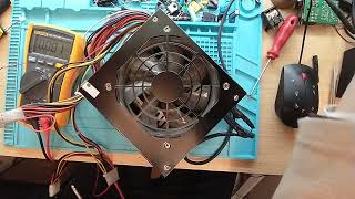
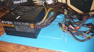
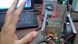
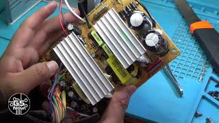
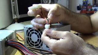
Continuing a bit with the issue regarding PC source repairs, this time I bring a technique to quickly identify the failure. As the repairs of PC power sources vary depending on the type of failure, what we should always do is identify the type of failure, and then raise possible solutions and we will become familiar with how to repair and diagnose the failure in these equipment. So today I want to show you how to apply this technique, the PC power sources have two main stages that we can interpret as a black box, where we have an input and several outputs or in technical language would be the primary and secondary, the primary is where the Alternating voltage (AC) or network connection enters, it transforms that voltage AC to DC, to a DC voltage of approximately 320 VDC, and then introduce it to a transformer that would generate the output voltage (secondary), but to generate the secondary voltages it is necessary that this signal is pulsing or variant in time, since a transformer does not convert DC voltage, this is achieved by means of electronic switches, which are usually transistors or mosfet, the most common is the MJE13007 transistor, the commission to activate and deactivate these devices are the PWM, which verify the status of the electronics in general, in case it finds an anomaly, the PWM gives the order to send to pay the electronics and therefore our equipment would not work, but it is due to the protection of the PWM. Already having the idea of how a power source works, we can attack the possible solutions. What I always do is check two output voltages (secondary), the standby (purple) and the power on (PW_ON, green), both must measure 5 VDC, or at least very close to 5 VDC, if this 2 voltages are present, it means that a large part of the primary is working in the correct way, otherwise the primary stage should be revised; the next step is to turn on our source, to turn it on we make a jumper or short between GND (black color) and power on (green color), if our source does not respond is that the PWM is detecting a short and we would have to check the electronic devices in the exit stage, in case our source starts, we measure all the output voltages and little by little we introduce load, again we monitor all the output voltages, if this voltage starts to fall, we have consumption problems, this fails for the capacitors usually give it and we would have to check both the ESR and the capacitance of these 2 devices, with a parameter that is outside their optimal conditions, it is necessary to replace it. In this repair we had 2 source of power, one with failure in the primary stage and the other in the secondary stage; The way in which it was identified that the fault was present in the primary stage, was during the verification of the standby voltage and power on, in this source it was determined that a resistance of 2 MΩ was open, when replacing the power supply function of the correct way, on the other hand the source that presented the failure in the secondary stage generated the power on and stand bye voltages, in this source when making the jumper it did not turn on, it found two defective 1000μF / 10V capacitors, these They were replaced and the fountain worked perfectly.
In this channel you will find all kinds of repair from the simplest to the most complex, but the most important thing is that you learn how to repair your electronic equipment, so the invitations to subscribe, activate the bell to be pending notifications, so be alert when upload a new video.