IDEAL TightSight Clamp Meter - Resistance and Continuity

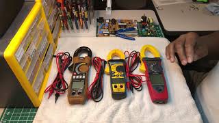
In this video we are going to look at the IDEAL TightSight Series of clamp meters. Specifically, the resistance and continuity functions. In both functions the tester will measure the resistance of an electrical circuit and I will show you the difference between them.
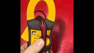
To do this, install the black lead into the common port and the red lead into the red port. A good safety tip is to check to make sure your tester is working properly. We can do that by turning the tester to the continuity function or the audible symbol and touching the test leads together. The meter is measuring resistance and the display drops to near zero ohms and an audible tone is heard. This tells us that the meter is working, the test leads are good and safe to use and we can now go take some measurements.
A continuity test is the checking of an electrical circuit to see if it is a continuous loop. It is measured in OHMs and the lower the resistance the more easily current can flow in the circuit. I can quickly check that this single pole light switch is working by checking its continuity. When I touch the leads to the two contacts the meters display drops to zero and we hear the audible tone. This tells me the light switch is turned on and is working properly. When I turn the switch to off and make that same test the meter display reads OL or over limit and no audible tone is heard. This indicates that the measured resistance is beyond the range of the meter. I can check the continuity of this small fuse and as you can see the display drops to zero and we hear the audible tone so the fuse is good. Electricians simply listen for the audible tone when checking a circuits continuity and do not have to look at the display. Keep in mind that since you will hear the buzzer for any value below about 30 ohms, it is important to look at the displayed value. A fuse that ‘sounds’ good because of the buzzer, may not ‘Look’ good because of a measured 20 ohms of resistance!!
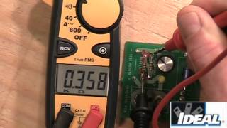
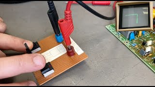
Next turn the selector knob to the Omega symbol or resistance and again touch the leads together. The meters display drops to close to zero resistance and no audible tone is heard while in this function. We can show a couple of examples of using the tester to measure the resistance of a circuit using this small tester training board. Here we have 4 resistors, a 6 Ohm, 100, 220 and 374 Ohm resistor wired in a parallel circuit and the same 4 resistors values wired in a series circuit next to it. By placing the black lead on the common pad and the red lead on pad 2 we can read the total resistance of the 4 resistors wired in parallel which is about 5 and a half Ohms. In a parallel circuit we would expect the total value to be slightly less than the lowest value resistor which was 6 Ohms. If I move the red lead to pad 3 we can read the resistance of those same four resistor values but now wired in a series circuit which is about 700 Ohms. In series circuits we simply add the value of the 4 resistors to find the total value of the resistance of the circuit.
In both functions the tester is measuring resistance and you will notice if we switch back to the continuity function when we test the series circuit the meter again shows about 5 and a half Ohms and we hear the audible tone. Moving the red lead to the pad 3 you again can read the 700 Ohms but no audible tone is heard. The tester only emits the audible tone at about 30 Ohms and down which is considered to be a circuit with continuity.
Using the resistance and continuity function of a TightSight meter an electrician can quickly determine the integrity of an electrical circuit.
Thanks for watching I am Ron with IDEAL and I will see you on the next one.
#RonKipperDatacomm #TightSight #ClampMeter #clampmeter.com