How to Make a High Performance Battery Charger Circuit (Used LM358 Opamp) [NEW]

How to Make a High Performance Battery Charger Circuit (Used LM358 Opamp) [NEW]
$2 for 14 layer PCB and PCBA from $0Free Setup, Free Stencil ) :https://jlcpcb.com/DYE
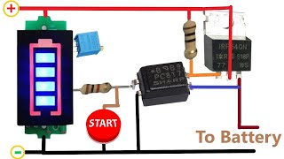
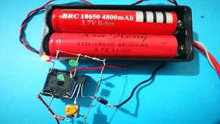
Hello, I am sharing a very high quality battery charging circuit with you. The heart of the circuit is the LM358 opamp integrated. It makes the system work very precisely by making comparisons.It is one of the most stable circuits that can be made using minimum components.
Don't forget to subscribe if you haven't subscribed yet. thanks for watching
Advantages
1 high sensitivity
2 Fast and precise reaction time
3 Informing about the status with LED (charging / Battery Full)
4 Thanks to the relay, it is possible to draw up to 10 Amps.
5 It is possible to charge a 6 volt battery using a 5 Volt Relay.
Disadvantages
1Instability problem in low quality batteries (caused by the sudden rise and fall of the voltage)
2 Initial setup and calibration can be confusing for some people.
Circuit Diagram__________________:
https://drive.google.com/file/d/1MSh3...
Download Gerber File__________________:
https://drive.google.com/file/d/1LA1...
❤ Our Second Channel : / @zaferyildiz5252
MATERIALS____________________________________________:
1X LM358
1X 12V or 6 V Relay
1X BC547
2X 1N4007
1X 6A10 Diode
1X 3 V Zener
1X 10k MultiTrimpot
3X 10K Resistance
2X 1K Resistance
2X Led ( Red Light / Green Light ) Don't worry we won't play squid game just for indication
#Jlcpcb
#LM358
#12VBatteryCharger
Thank You JLCPCB For Sponsoring My Video.

![[New] Adjustable Voltage power supply 55 V 20A High Power and Current / Automatic Fan On/Off](https://i.ytimg.com/vi/Q37LbVuXrRo/mqdefault.jpg)