Duct Design for Great Results w/ Ed Janowiak (ACCA)

Ed Janowiak of ACCA gives a presentation about fan and duct design, system testing, and Manual D at the second annual HVACR Training Symposium. Learn more about the 2022 HVACR Training Symposium at https://hvacrschool.com/symposium/.
Ed has over 35 years of HVACR experience, both in the field and through teaching. He has lived and done business in New Jersey, which has a variable climate, and he has experienced a wide range of temperatures.
When designing ductwork, we obviously want our static pressure to be close to our calculations. However, lower static pressure is usually more desirable than higher static pressure. When static pressures exceed our expectations, we have to start removing elements of our design.
The real key to good duct design is managing the occupant’s expectations. Understand what the client wants, but you must be upfront with what they can and cannot expect from their HVAC system.
Manual D requires that you pick a fan and design the ductwork around the fan. Ducts must accommodate fan pressure. (Manual Q is the opposite; you choose the fan based on the duct resistance.) Manual D’s goal is to calculate the critical path, which is the longest circulation path in the system. It’s also a good idea to comply with local codes, but it is not responsible for a design’s predictability.
To design a duct system, we also need to know how much BTUH (BTUs per hour) and CFM (cubic feet per minute) need to be delivered. We can get these figures by finding the BTU gain and loss (Manual J), and we can use Manual S to calculate our target airflow. Take the SHR (sensible heat ratio) into account, and you use all of that data to find your capacity.
We should refer to the friction rate worksheet to develop a good duct design. You initially take your external static pressure and CFM readings. Then, you discover and note the component pressure drops. You also take available static pressure and total effective length into account. In the end, you will figure out your friction rate. The purpose of that worksheet is to determine the friction rate based on the duct system’s critical path.
We use manometers to take static pressure measurements. Static pressure is NOT velocity; it is the measure of pressure against the walls of the duct. You can use static pressure as an airflow indicator.
Several components can contribute to pressure losses in the critical path, including heat exchangers, UV lights, grilles, and dampers. However, the filter is the most notorious source of pressure drops. When sizing a filter, you need to know CFM, velocity, and area. The system must have enough pressure to overcome those drops in the system.
Once you have calculated your external static pressure and losses, you can subtract those losses from your external static pressure to yield your available static pressure.
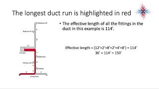
You determine your total effective length by adding the supply and returnside total effective lengths together (including trunks, runouts, and group fittings of each one’s critical path). Then, to get the friction rate, you multiply your available static pressure by 100 and divide that product by the total effective length. (You should also be able to find that value on a chart on the friction rate worksheet.)
Humans feel comfortable when they don’t notice their surroundings. So, excessive fan noise can be an unexpected source of discomfort for occupants. Watch your air velocity to avoid creating that humming sound with the fan. Don’t start off at high speed! Manual D gives us maximum air velocity guidelines to avoid comfort issues. Manual T also covers terminal velocity and grille selection, which heavily contributes to comfort. (A grille should be located in a sensible location and should have the proper throw. Grille size will determine the distribution box size.)
You must determine your heating and cooling factors to begin working on your duct design worksheet. The heating factor is the blower CFM divided by your Manual J heat loss; your cooling factor is the blower CFM divided by your Manual J heat gain.
When you use effective length charts, you must keep in mind that those effective lengths will only contribute to duct behavior predictably under a certain set of conditions. If you’re running at a slower fan velocity the friction rate will change, and you will need to do some more calculations. As friction goes up, effective length goes down.
Our external static pressures may end up higher than we anticipated due to excess length (with flex duct).
Ed also discusses:
Alternative ways to measure static pressure
Heighttowidth ratio of ducts
Design software pitfalls
Return drop sizing
Sizing for flex duct systems
Round registers
Grille air velocity and sizing
Filter sizing
Standard test airflow rates for MERV ratings
Read all the tech tips, take the quizzes, and find our handy calculators at https://www.hvacrschool.com/.