Creating MOVING HINGE JOINTS in Autodesk Fusion 360 with the Revolute Joint!

In today’s video, we’re going to start a new series on assemblies and joints inside of Autodesk Fusion 360. These items, when combined, can be used to simulate motion and the way objects will interact inside of the real world.
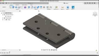
In this first tutorial, we’re going to learn how to create a hinge joint using assemblies.
The first thing to note when you’re doing this is you need to make sure you’ve created your objects that you want to simulate as part of a joint as components.
This is fairly simple – either when you first create your object, make sure to select the option for “new component,” or you can also select your objects that you’d like to make into a component and right click and select the option for “create component from bodies.”
Once you have your objects created as components, we can start creating our joint.
To do this, we’re going to use the assemble function inside of fusion 360 – click the “assemble” dropdown, then click on the button for “joint.” This allows you to dictate the relationship between objects inside of fusion 360.
Notice that the joint function gives us the ability to select 2 different components. These are going to be the 2 components that are going to interact in our joint. Notice that when you mouse over a component, you get a little circular marker that shows up wherever your mouse goes. This is going to dictate the points from which your joints interact. In this situation, for example, we want our component one joint to be at the inside of one of our hinge joints.
Make sure the marker is standing up when you do this and mouse over the center of one of our joints.
Click this point. Then, mouse over the point again to set this point for our second object. We’re basically setting a base point for our interaction.
Now that we have both objects selected, let’s set the kind of motion that we want our joint to have. In this case, we want our joint to be a revolute joint, or a joint that rotates around a point. Under type, set this, and if you need to, you can set your rotation axis to be the Zaxis. If you click the “animate” button, Fusion 360 will animate a preview of your joint moving.
It’s moving too far right now, but we’ll fix that in a moment. For now, if everything seems to be running well, let’s go ahead and click “ok.”
Notice that once we click ok, we get dropped back into our regular working view. However, now we can click and drag this hinge and it moves around. However, we still have a problem – you can take this hinge and rotate it but it goes through the other hinge.
In order to fix this, what we need to do is to set a joint limit, or a limitation on how far the joint will go. To do this, you can right click on your joint and select the option for “edit joint limits.”
This will allow you to set your minimum and maximum limits for how far the joint will rotate. You can either type values into the minimum and maximum, or you can also drag the little flags to the min/max points.
Once you’re done, click ok.
Notice that now, when you move your joint around, it stops at the number of degrees that you dictated.
If you want, you can do the same thing for your other joint as well.
That’s where I’m going to end this video.