Variable Frequency Drives Explained | VFD Basics - Part 1

▶ C'mon over to https://realpars.com where you can learn PLC programming faster and easier than you ever thought possible!
▶ You can read the full post here
https://realpars.com/variablefrequen...
⌚Timestamps:
00:00 Intro
00:15 AC motor rotational speed
00:54 Speed reduction
01:45 VFD
02:23 VFD applications
03:05 VFD working
03:45 Sixpulse rectifier or converter
05:18 DC bus or DC filter and buffer
06:57 IGBT
=============================
In this video, we will learn about VFD and its applications. We will also cover in detail the converter and the DC link.
Induction or alternating current electric motors rotate at a rate that is set by the number of poles inside the motor itself, and the power supplied.
The frequency is directly related to the RPM of a motor. The higher the frequency, the faster the RPM or the higher the engine rotation speed.
In the United States, electric power utilities provide alternating energy with a frequency of 60Hz. A standard twopole AC motor operating at this frequency provides a nominal rotation of 3600 RPM.
If an application does not require an electric motor running at full speed of 3600 RPM, which is very common, a few solutions exist:
– Using a mechanical speed reducer decreases the output speed by increasing torque – the output gear has more teeth than the input gear. They require lubrication, provide no flexibility, are subtle to vibration and noise, and are not suitable when shafts are distant.
– Adding more sets of poles reduces the speed without altering it electrically. Currently, there are transistor systems that allow for poles inside motors to be turned on and off. However, those systems can be complex and don’t provide fine control.
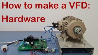
– Using a Variable Frequency Drive (VFD) can be configured and finetuned to generate a ramp, frequency, and voltage so that the motor operates according to the load requirements (desired speed and voltage).
An important feature of the variable frequency drive is that as the motor speed requirements in a given application change, the drive can simply raise or lower the motor’s speed in order to meet new operating requirements.
The use of VFDs is widespread in numerous industrial and commercial applications.
– In industrial applications, VFDs are used to control from extruders, and electric cranes, to roller coasters, and mechanical bulls, with so much in between!
– In commercial applications, VFDs are widely used in pumps to control flow and even volume in a tank, as well as in the HVAC industry, being considered green technology.
Ultimately, a VFD varies the supplied frequency to an AC motor in order to control its speed; allowing a smooth startup, and adjusting motor speed as the application requires.
Let’s dive into the How does a VFD work?
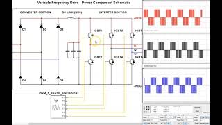
1) A sixpulse rectifier or converter is where the threephase alternating current gets converted into direct current by the use of diodes.
When we connect a threephase alternating current to the converter:
– When phase A is greater than phase B or C voltages, this diode opens, allowing current to flow,
– When phase B becomes greater than phase A, then it is phase B diode that opens while phase A diode is closed,
– The same is true for C, as well as for the three diodes on the negative side of the bus.
That results in six pulses of currents as each diode opens and closes. The resultant waveform will look like this:
2) The DC bus is represented by only one capacitor and resistor on the diagram, but in reality, there are various capacitors and resistors associated in series and in parallel.
Since the capacitors are not charged, their impedance is very low. If we were to charge them, the initial inrush could damage the input power devices, or the rectifier/converter, in case the entry fuses didn’t interrupt the circuit.
So instead, we have a precharge circuit. Precharge is a current limiting circuit that slows the charge rate of the bus capacitors during powerup.
3) IGBT is the last step of the drive output: the DC to AC converter and our PWM output.
=============================
Get a RealPars pro membership: https://learn.realpars.com/bundles/pro
=============================
Missed our most recent videos? Watch them here:
https://realpars.com/lvdt
https://realpars.com/pressuretransducer
https://realpars.com/endofarm_tool
=============================
To stay up to date with our last videos, make sure to subscribe to this YouTube channel:
http://bit.ly/realpars
=============================
TWEET THIS VIDEO: https://ctt.ac/4tL9Y
=============================
Follow us on Facebook / therealpars
Follow us on Twitter / realpars
Follow us on LinkedIn / realpars
Follow us on Instagram / realparsdotcom
#RealPars #vfd #ACmotor