Understanding Low Voltage Wiring for AC u0026 Heat Pumps 3D

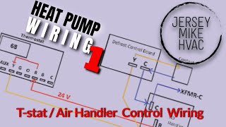
This 3D video shows how low voltage wiring works in a typical heat pump system. We cover schematics, some electrical circuit basics, how the lowvoltage circuit accomplishes its tasks, and some best practices to maximize the longevity of your lowvoltage circuits.
There will be three diagrams: the condenser, heat strips, and air handler each having its own schematics.
Those ac schematics show various types of switches, including basic switches, pressure switches, thermal switches, float switches, and contacts. An open switch has no electrical path, meaning that the equipment can't turn on. On the other hand, a closed switch allows electricity to pass through, so the equipment can turn on. Switches will be either in the normally closed or normally open position, and the schematics will indicate the normal state of the switch. It's also worth noting that switches are powerpassing devices and do not use or consume electricity. In the condenser, you will see high and lowpressure switches. The heat relay on the heat strips will have a prominent pair of normally open contacts. The air handler usually has a normally closed float switch, which opens when water fills it up and breaks the circuit.
Compared to switches, loads are powerconsuming devices that transform electrical energy into some other form of energy. The contactor coil and reversing valve solenoids are examples of loads.
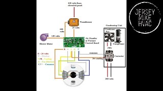
Within the thermostat, G (green) goes to the blower, Y1 (yellow) is for the contactor, O/B (usually orange, sometimes dark blue) is for the reversing valve, RH (red) is for constant 24v heat (RC is constant 24v cool), C (blue) is for common, and W2 (white) is for auxiliary heat. In this case, we are using ACC+ (black) for dehumidification.
The transformer is the source of the 24v power that starts everything. Transformers take high voltage (often 230v) from the power company on the primary and drop it to 24v on the secondary, which then goes to the integrated circuit board. The primary and secondary interact electromagnetically; they don't actually touch.
When the 24v power makes it to the integrated circuit board via SEC1 or SEC2, it passes through the 5amp fuse and powers the R terminal on the terminal block. Due to that configuration, many techs wire the float switch to break R. Breaking R will stop power to the thermostat and the defrost board at the condenser. (However, some techs may break Y instead.)
Y goes from the thermostat to the terminal block and then to the contactor coil. The contactor coil needs 24v to pull the contactor in and close the contacts that allow power to reach the compressor and the condenser fan. Y goes in and out of the high and lowpressure switches before reaching the contactor coil.
W2 connects to the heat strips and W on the defrost board from the terminal block. So, either the thermostat or the defrost board has the capability to bring on electric heat.
The G terminal supplies constant 24v power to the blower fan inside the air handler.
Common feeds from the common side of the transformer and goes to the thermostat to complete the circuit. It then provides 24v common to the defrost board, which also completes the circuit on that side of the unit. We need common in all cases because it provides a path back to the transformer; otherwise, the circuits would all be open and would not work.
The O terminal's wire passes through the terminal block from the thermostat. Then, the 24v power goes to the condenser to energize the reversing valve solenoid in cool mode. (Note: Ruud and Rheem systems energize the reversing valve solenoid in heat mode, and these may have dark blue instead of orange wires.)
When we use ACC+ for dehumidification, the blower will only reach full speed when the DH terminal is energized on the terminal block.
When stripping back the wire jacket, try to minimize nicks by making a small vertical cut and pulling the sheath back. Cut the sheath you've pulled back. Cut the tips of the conductors, as you may have nicked them. Make careful cuts to expose the bare conductors; you want them to be able to reach the terminal block or touch under the wire nut, but they shouldn't be exposed.
When routing wires or cables through cabinets or other areas where they might get cut, be sure to use proper grommets. Don't run wires over metal objects like the capacitor, as shorts may occur. When routing the wires in a spot where they might chafe, rub out, or otherwise suffer damage, use a conduit whenever possible to protect the wires. Also, use zipties to secure wires with a bunch of slack.
Short circuits happen when there is an undesigned path, and open circuits happen when the path is interrupted completely. Try to minimize both as much as possible.
Read all the tech tips, take the quizzes, and find our handy calculators at https://www.hvacrschool.com/.
Learn more about the 2022 HVACR Training Symposium at https://hvacrschool.com/symposium/.