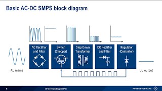
Howto repair switch mode power supplies #2: Stand-by circuit and its functionality

In the second video in the series of repairing switch mode power supplies (SMPSs) we look at the importance and the functionality of the so called Standby circuit. Namely, the low power Standby circuit is responsible for generating the Standby voltage, which should be always generated by the power s
upply unit (PSU) as soon as your device is plugged into the power grid. This is because the standby
voltage is feeding those circuits (most of the time microcontrollers) which are checking the state of
your device and they are waiting for a turnON signal. After a microcontroller receives the turnON
signal, again the standby power is used to send the wakeup signal to the high power portion of the
Switch Mode Power Supply.
Therefore, whenever you try to repair a switch mode PSU, firs you have to make sure, that the Standby power section of the PSU is working properly, and it is providing the right voltages to the standby circuit. This is because if there is no standby power, the device will never able to turn on.
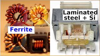
The Standby circuit it mostly formed by a small transformer, a mediumpower FET transistor and an in
tegrated circuit, which is controlling the gate electrode of the FET.
Thus, if you are able to spot a small transformer on the printed circuit board of your switch mode PSU you are trying to repair, you can be almost sure that it is the standby transformer.
In this video I introduce the notion of pulse width modulation (PWM), but this is the most important
topic for switch mode PSUs, so I will cover it in the followup video.