How A Typical Refrigeration Cooler Works - Pump Down Refrigeration in 3D
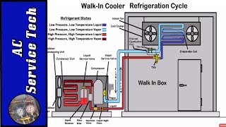
In this 3D video, we show how a typical refrigeration cooler works and focus on pump down refrigeration. This video is narrated by Corey Cruz (BadTXV on TikTok) and shows the refrigeration cycle and automatic pump down for a mediumtemp R404A walkin cooler.
Automatic pump down is a common control strategy used in refrigeration. It automatically pumps refrigerant on the low side of the system into the condenser and receiver whenever there isn't a call for refrigeration; common scenarios include the defrost cycle and when the box temperature has been satisfied.
Pumping a system down protects the compressor by preventing refrigerant migration during the off cycle and keeping vapor refrigerant from cooling and condensing to a liquid in the compressor. Liquid refrigerant in the compressor can severely damage the compressor, including causing mechanical wear and flooded starts.
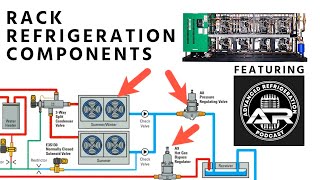
An automatic pump down system has three main control components: thermostat, liquid line solenoid, and lowpressure controller.
The thermostat is typically mounted at or near the evaporator head unit in the box. Its sensor reads the return air temperature. The thermostat's relay contacts close on a rise in temperature, causing power to pass through the contacts to the liquid line solenoid.
The liquid line solenoid (or pump down solenoid) is installed on the liquid line of the system and may be at the evaporator or condenser. During a call for refrigeration, the liquid line solenoid will be energized and will open to allow the flow of refrigerant. It closes during the off cycle and prevents refrigerant flow. The receiver, liquid line filter drier, and sight glass usually come before the liquid line solenoid; a receiver stores excess refrigerant, a liquid line filter drier removes contaminants, and a sight glass will let you know if there is a full line of liquid going to the liquid line solenoid and metering device.
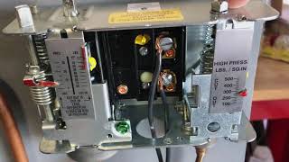
The lowpressure controller is installed at the condenser and will be wired in series with the contactor coil. It will cut in or out based on pressure conditions. When setting the cutin and cutout setpoints, you will need to consult the manual and be aware of the refrigerant used in the system. To obtain the cutout setting, subtract the differential from the cutin setting.
When the box temperature rises above the thermostat set point, the thermostat relay's contacts will close and allow power to travel to the liquid line solenoid, which will then open and allow refrigerant to pass to the evaporator. With refrigerant flowing and the pressure rising, the pressure on the low side should then exceed the cutin setting on the lowpressure control. The contactor coil should then close, completing the circuit and allowing the compressor and condenser fan motors to start operating. During the off cycle, this process is reversed, and the contacts open to remove power to the liquid line solenoid.
Pump down begins with the compressor and condenser fan still running. When the suction pressure reaches the cutout setting, the contacts in the pressure controller open and deenergize the contactor coil, turning the compressor and condenser fan motors off.
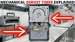
Many mediumtemperature applications don't have a defrost clock and merely defrost during the off cycle. 120v singlephase line power will energize the evaporator fans, liquid line solenoid, and thermostat; the evaporator fans will continue running during the off cycle, and it will supply power to the terminals and their respective wires to the components on the low side of the system. The condenser will receive 208v threephase power.
When the box setpoint is satisfied, or the system is in defrost, the thermostat will prevent power from energizing the liquid line solenoid. Refrigerant will not pass to the evaporator coil, and excess refrigerant will collect in the liquid line receiver. The pressure will drop on the low side of the system; the pump down procedure will continue until the pressure reaches the cutout setting. The power will then be removed from the compressor and condenser fan motors.
Buy your virtual tickets or learn more about the HVACR Training Symposium at https://hvacrschool.com/symposium.
Read all the tech tips, take the quizzes, and find our handy calculators at https://www.hvacrschool.com/.