CO2 Refrigeration Rack Overview

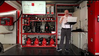
Kevin Compass joins HVAC School to give an overview of a transcritical CO2 refrigeration rack. He goes over its primary components during a commissioning procedure on a new system and talks a bit about charging a CO2 system.
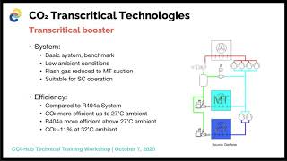
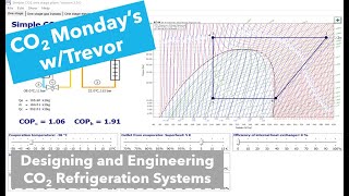
CO2 has a triple point and a critical point within its operating range. The triple point is the lower threshold at which CO2 may exist as a solid, liquid, or vapor, so we have to keep the pressure above the triple point to prevent it from solidifying. (CO2 is often charged in the liquid state under pressure.) The critical point is at around 87 degrees Fahrenheit, and CO2 will become a transcritical fluid (which is neither liquid nor vapor and doesn't obey the rules of saturation). As a result, transcritical CO2 systems have a gas cooler instead of a traditional condenser. In conditions below 87 degrees, a gas cooler will function as a condenser; otherwise, it has to drop the pressure of the fluid to get it to condense.
The system in this video has a 3/8" charging line, which takes new refrigerant in the liquid phase; during charging, you have to watch your vessel pressure to make sure you don't hit the relief point.
The charging tanks have a dip tube to allow for charging in the liquid state. Once the sight glass stops flashing, we can disconnect the tank.
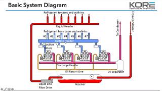
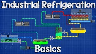
This system has a suction transducer, which measures pressure on the suction line. It also has a coil temperature sensor for defrost termination. On systems where the lowtemperature and mediumtemperature cases are on the same rack, the lowtemperature compressors discharge into the suction line for the mediumtemperature cases. The mediumtemperature compressors discharge into the discharge line, which travels to the gas cooler. The compressors also have an oil system, which consists of a separator (coalescing, in this case), oil level regulators, and a reservoir (with an oil level sight glass and an oil level alarm). The reservoir is always maintained under pressure and vents off to the flash tank.
The lowtemperature side of the system has an accumulator, transducer, and lowtemp suction header. There is also a copper mediumtemp discharge header. The high side of the system has a pressure gauge and a highside relief valve, and the flash tank has relief valves, a bypass valve, a pressure gauge, transducers, a flash gas bypass valve, and an oil line bypass. Pressure is often measured and regulated using the bar scale, not PSI.
A heat reclaim valve allows the system to use compressor discharge gas for reheat at the main RTU. More pressure transducers limit the pressure drop to the reclaim condenser.
The gas cooler in this video has four ECMs and fans; it acts as a condenser when the temperature is below 87 degrees. The gas cooler also has a drop leg, which is the line between the condenser/gas cooler and the receiver. There is also a high pressure regulating valve and a flash gas bypass valve. Those valves work together to hold back and then vent off the gas to get the CO2 to condense back down; that keeps the flash tank at a certain pressure. The flash tank drops temperature and pressure at the same time.
The system also makes use of suction drier shells and hot gas injection, which injects hot gas into the mediumtemperature suction side to regulate the superheat. If the superheat gets too high, the liquid injection valve helps desuperheat the mediumtemp side.
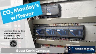
The main electrical panel contains CPC (Emerson) controls, and the digital compressor controller uses pulsewidth modulation. It also has a normal compressor contactor and a valve driver for the CO2, which manages communication between the valves. Boards monitor the dry contacts for the switches, sensors, and analog outputs. The main controller displays all of the display temperatures and the sensor data; each case has its own sensor and solenoid valve, which is managed and monitored by the main controller.
The two lowtemperature compressors are scrolls, and the two mediumtemperature compressors are of the semihermetic reciprocating variety. The rack is transcritical and compresses CO2. When the CO2 discharges out of the lowtemperature compressors, it gets sent to the mediumtemp suction header. That configuration reduces the compression ratio and improves capacity as a result. The compressors are controlled by a Danfoss VFD.
Podcast w/ Emerson on CO2:
https://www.hvacrschool.com/co2/'>https://www.hvacrschool.com/co2/
Podcasts w/ Hill Phoenix on CO2:
https://www.hvacrschool.com/critical...
https://www.hvacrschool.com/3flavors...
Read all the tech tips, take the quizzes, and find our handy calculators at https://www.hvacrschool.com/